

Power Supplies, Terminal Blocks & Relays.
Every control panel, whether it runs a small packaging line or a full industrial process, rests on the same three engineering decisions: how power comes in, how it is wired and protected, and how loads are switched. A weak choice in any one of them shows up later as nuisance trips, overheated terminals or a relay that fails early in service.
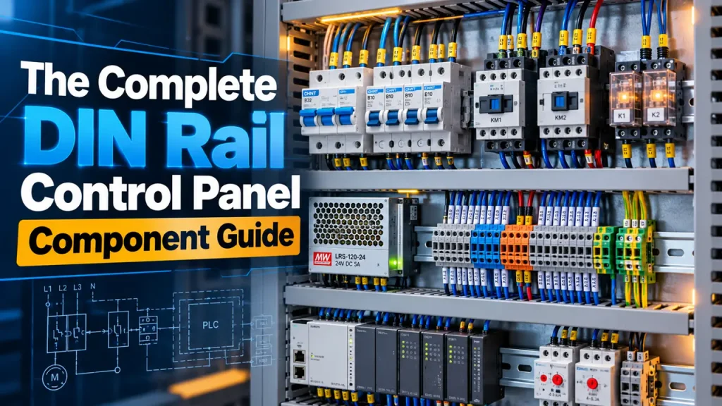
This guide follows the order in which you would specify a real panel: power supplies, terminal blocks and relays, with the practical selection criteria and DIN rail hardware details you need to make the right call the first time. It is written for the panel design engineer, the system integrator, the consultant and the end user, and covers panels in power distribution (HT, LT, MV and APFC), building management (HVAC and BMS), oil and gas and other continuous process automation, railways and machine building.
Powering the Panel: Choosing the Right DIN Rail SMPS
Almost every modern industrial control panel needs a reliable DC source for its control and automation components. A DIN rail power supply, typically a switch-mode power supply (SMPS), mounts directly on the rail and converts incoming AC power into regulated DC for PLCs, sensors, relays, I/O modules, HMIs and other control devices, while saving panel space.
Why AC-DC SMPS Are Preferred Over Linear Supplies
An AC-DC SMPS converts energy using high-frequency switching and power-conversion circuitry, rather than continuously dissipating excess voltage as heat, as a conventional linear regulator does. The practical benefits are:
- Higher efficiency, which means lower power losses, less heat and lower energy consumption over the operating life.
- Smaller size, lower weight and high power density, which help reduce panel footprint.
- Wide input-voltage ranges on many industrial models, allowing operation across varying mains conditions.
24 VDC Power Supplies: The Common Industrial Choice
24 VDC power supplies are the most common choice in industrial control panels because:
- Many PLCs, sensors, I/O modules, relays, contactors and other automation devices are available with 24 VDC operation.
- It offers a practical balance between voltage drop, conductor size and component requirements.
- It suits many control and instrumentation applications where extra-low-voltage circuits are preferred.
When specifying a DIN rail power supply, 24 VDC is a sensible starting point, but the output voltage should always be determined by the connected equipment.
Sizing It Right: Matching Wattage to Load
Correct sizing is one of the most important steps in selecting a DIN rail SMPS. An undersized supply may enter current limiting or overload protection, cause output-voltage instability, or fail to start the connected equipment reliably. Excessive oversizing, on the other hand, adds cost and consumes panel space without a meaningful benefit.
Start by calculating the maximum continuous DC load current, then select a supply with enough capacity for startup and inrush current, peak or transient loads, ambient-temperature derating and future expansion.
The table below shows representative power classes at 24 VDC:
| Model Class | Typical Output Current | Best For |
| 60W SMPS | ~2.5A @ 24 VDC | Small panels with PLCs, sensors and a limited number of relays |
| 120W SMPS (5A SMPS) | 5A @ 24 VDC | Mid-size panels with multiple I/O modules and instrumentation |
| 240W SMPS | 10A @ 24 VDC | Larger panels running multiple contactors, drives, or HMI and PLC combinations |
Note: These are representative power classes, not universal classifications. Actual available ratings vary by manufacturer and product family.
A Practical Sizing Approach
For a panel design engineer, this calculation belongs in the design documentation, so the supply rating can be traced back to a stated load list and margin.
Total DC load current = sum of the operating currents of all connected loads
Then compare the result with the supply’s peak and inrush behavior. For example, a SMPS 60W unit that regularly carries a load close to its rated current leaves little margin for inrush or high ambient temperature, so the next rating up, such as a 5A SMPS, is often the safer choice.
Don’t Size Only by Watts
Two supplies with the same nominal wattage can behave differently under real operating conditions. Also compare:
- Input voltage range and output voltage adjustment range.
- Efficiency and power factor, where applicable
- Overload and short-circuit protection
- Installation clearance and ventilation
- Hold-up time
- Ripple and output-noise specifications
- Required certifications and applicable standards.
Redundant Power: The Diode O-Ring
In panels where a supply failure would stop a critical process, which is a decision usually made by the end user or the consultant setting the availability requirement, two supplies are often connected in a redundant arrangement. A diode O ring (also written OR-ing diode) is the element that makes this work: each supply feeds the common 24 VDC bus through a diode, so if one supply fails or is switched off, the other carries the load and the failed unit cannot pull the bus down.
- Each supply in a 1+1 arrangement should be sized to carry the full load on its own.
- Diodes add a small voltage drop and dissipate heat, so allow for both in the panel layout.
- A dedicated redundancy module is generally neater than discrete diodes, and is easier to monitor.
- Confirm in the datasheet that the selected supplies are suitable for parallel or redundant operation.
Wiring & Protection: Choosing the Right Terminal Block
Once electrical power and signals enter a control panel, they must be distributed, connected, protected and, where required, isolated across dozens or even hundreds of wiring points. This is where terminal blocks play a critical role.
Terminal block choice affects the system integrator directly, because it sets wiring time, test points and fault-finding effort during build and commissioning. The right choice depends on the required function, protection, connection technology, current and voltage ratings, conductor size, installation environment and maintenance requirements.
Fuse Terminal Block: Protection at the Connection Point
A fuse terminal block combines a terminal connection with an integrated fuse holder, allowing individual circuits to be protected close to the point of connection, which simplifies panel architecture.
Use a fuse terminal block when:
- Individual circuits, such as sensors, actuators and control branches, need dedicated overcurrent protection.
- Panel space is limited and integrating protection at the terminal level is advantageous.
- Easy visual identification and replacement of the fuse is important.
The fuse, rated voltage, rated current and breaking capacity, and coordination with the upstream protection, must always be selected according to the application.
Feed Through Terminal Block: The Workhorse Connection
A feed through terminal block provides a straightforward electrical connection between conductors, typically allowing a conductor entering one side of the terminal to be connected to a conductor on the other. It is one of the most widely used terminal-block functions in control panels, machinery and industrial installations.
Use a feed-through terminal block when:
- You need a reliable, organized connection between field and internal wiring.
- The circuit does not require integrated fusing or switching.
- High wiring density and clear circuit identification are important.
- Cross-connections or other terminal-block accessories may be required.
Push-In Terminal Block: Speed Without Tools
A push in terminal block uses spring-clamp technology instead of screws: you strip the wire and push it straight into the terminal, where an internal spring holds it under constant pressure. Push-In technology is available across terminal block functions, including feed-through and fuse types, and manufacturers report substantial reductions in connection time compared with conventional screw-clamp technologies.
Use a push-in terminal block when:
- You are wiring high-volume panels and want to reduce assembly time
- The installation is exposed to vibration (motors, mobile equipment), where screw terminals can loosen over time
- You want consistent connection quality that does not depend on the technician’s screw-torque discipline
Quick Decision Table
| Requirement | Terminal Block Function | Possible Connection Technology |
| Simple wire-to-wire connection | Feed-through | Push-In / Spring / Screw |
| Individual circuit protection | Fuse terminal | Push-In / Spring / Screw |
| Circuit isolation and testing | Disconnect / test terminal | Push-In / Spring / Screw |
| Protective earth connection | PE terminal | Push-In / Spring / Screw |
| Many connections from one supply or signal | Distribution block | Push-In / Spring / Screw |
| Fast panel wiring | Any suitable terminal function | Push-In / Spring / Screw |
Switching & Control: Relays and Solid State Relays
The final piece is switching: deciding what turns loads on and off, and how reliably it does so.
Solid State Relay vs Electromechanical Relay
A solid state relay (SSR) switches a load electronically, using semiconductor devices instead of a mechanical contact. That is the core difference between an SSR solid state relay and a traditional electromechanical relay (EMR):
| Factor | Solid State Relay | Electromechanical Relay |
| Switching mechanism | Semiconductor (no moving parts) | Physical contacts |
| Switching speed | Very fast (typically microseconds to a fraction of a cycle) | Milliseconds |
| Mechanical wear | None | Contacts wear with switching cycles |
| Audible click | No | Yes |
| Heat in the on-state | Dissipates heat across the output device; may need heat sinking at higher currents | Very low contact losses |
| Off-state leakage | Small leakage current is present | None (open air gap) |
| Typical cost | Generally higher upfront | Generally lower upfront |
A typical solid state relay circuit has a low-power input stage, an optocoupler that provides galvanic isolation, and a semiconductor output stage that carries the load. With no contact bounce or wear, an SSR suits high-frequency switching such as PID-controlled heaters.
Solid State Relay DC Load Applications
A solid state relay DC load setup is common in DC motor control, LED lighting banks and battery-charging systems. Switching DC cleanly is difficult for mechanical contacts at higher voltages, because DC has no natural zero crossing to help extinguish an arc. An SSR avoids the problem by having no contacts to arc.
One point matters when selecting: the SSR output must match the load type. AC-output SSRs generally cannot be used to switch DC, so choose a DC-output SSR for DC loads, and check the load current, voltage and any inductive behaviour against the datasheet.
SSR and Relay Pricing: What Drives the Cost
Solid state relay price and SSR relay price depend on a few key factors:
- Load current rating: higher-current SSRs cost more because of larger semiconductors and heat-sinking needs.
- AC vs DC output type: the output device and its protection differ, which affects cost.
- Switching characteristics, such as zero-crossing or random turn-on.
- Isolation voltage and certifications: safety-critical applications may need higher ratings.
Rather than comparing unit prices alone, compare solid state relay price against total cost of ownership, since an SSR in a high-cycle application can outlast a mechanical relay.
Relay Modules and Pole Configurations
A relay module packages the relay with its base and an indicator LED, ready to mount on the DIN rail. Pole configuration is a key part of the specification:
- 1 pole relay: switches a single circuit, for simple on/off control of one load
- Single pole double throw relay (SPDT, 1CO in Connectwell notation): one common contact that switches between a normally open and a normally closed position, giving both make and break functions from a single pole
- 2 pole relay (2CO): switches two independent circuits at the same time from one coil signal, as a double pole double throw (DPDT) changeover
Where line and neutral are switched together, confirm that the relay ratings and applicable standards suit the application; a relay is not a substitute for a properly rated isolator.
Pin Counts and DIN Rail Sockets
Plug-in relays are commonly identified by pin count, which indicates the socket and wiring you will need. Typical examples are:
- 6 pin relay: a compact plug-in format, commonly a single-pole changeover.
- 8 pin relay: commonly a 2CO (DPDT) relay, the general-purpose choice for two independent circuits.
- 14 pin relay: commonly a 4CO (4PDT) relay, for more complex control circuits.
Matching the relay to the correct din rail relay socket is essential, and a mismatched pinout is one of the most common wiring errors at commissioning. Pin count alone is not enough, since pin layouts can vary between manufacturers, so always check the socket’s pin arrangement against the relay datasheet before wiring.
A well-planned din rail socket arrangement also simplifies maintenance: a failed relay can simply be unplugged and replaced without rewiring, provided the base socket stays on the rail. This is a real benefit for the end user, whose maintenance team can restore a function quickly without needing the original panel builder.
A din rail power socket is a different item: a service outlet mounted on the rail so that technicians can power a laptop or test equipment inside the panel. It should be fed from a suitably protected circuit and installed in line with local electrical standards.
2CO and 4CO Modular Relays: Models and Pin Configurations
Connectwell modular relays use CO (change-over) notation. A 2CO relay has two independent change-over contacts (DPDT) and plugs into an 8-pin socket. A 4CO relay has four (4PDT) and plugs into a 14-pin socket. Both use the rectangular general-purpose base, mount on DIN rail and are operated by a single coil (A1 and A2).
| Attribute | 2CO (8-pin socket) | 4CO (14-pin socket) |
| Contact configuration | 2 change-over contacts (DPDT) | 4 change-over contacts (4PDT) |
| Independent switching circuits | 2 | 4 |
| Load ratings | 5 A 7 A and 12 A (power versions) | 5 A and 6 A |
| Typical use | General control panel switching, two-circuit switching, interlocking | Complex automation logic, motor reversal, star-delta starter wiring, multi-signal switching |
| Relay model | CRLA2XXX | CRLA4XXX |
| Socket model | CRS2COY, CRS2COPY | CRS4OY |
| Relay with socket (modular relay) | CRMA series, e.g. CRMA2PP024DYLT (with test button) | CRMA series, e.g. CRMA4P024DYLT (with test button) |
Note: XXX in a relay model denotes the coil voltage and variant code. Relay and socket can be ordered separately or as a combined CRMA modular relay (CRMAXSXXXDYL format). Common accessories for both: CRB4M retainer bracket, CRLD pluggable LED module and MT-CRMXCO markers.
2CO (8-Pin) Pin Configuration
The 8-pin socket supports two independent change-over circuits controlled by one coil. The pin labels follow the standard contact numbering:
| Pin Label | Function | Circuit |
| A1 | Coil positive (+) | Control |
| A2 | Coil negative (−) | Control |
| 11 | Common (COM), pole 1 | Load |
| 12 | Normally closed (NC), pole 1 | Load |
| 14 | Normally open (NO), pole 1 | Load |
| 21 | Common (COM), pole 2 | Load |
| 22 | Normally closed (NC), pole 2 | Load |
| 24 | Normally open (NO), pole 2 | Load |
4CO (14-Pin) Pin Configuration
The 14-pin socket offers the highest contact density in one relay footprint. Its pins are arranged in tiers, with the contact labels for all four poles shown in brackets:
| Tier | Pins | Function |
| Top tier | 1, 2, 3, 4 | Normally closed (NC) contacts, all four poles (12, 22, 32, 42) |
| Middle tier | 5, 6, 7, 8 | Normally open (NO) contacts, all four poles (14, 24, 34, 44) |
| Bottom tier | 9, 10, 11, 12 | Common (COM) terminals, all four poles (11, 21, 31, 41) |
| Coil | 13 (A1), 14 (A2) | Control coil: connect the control voltage here |
For DC coil variants, connect A1 to the positive and A2 to the negative of the control supply. As with any socket, confirm the pin layout against the datasheet of the specific socket before wiring.
Din Mount Relay Considerations
A Din Mount Relay clips directly onto a standard 35 mm DIN rail alongside terminal blocks and the power supply, keeping the layout compact and standardized. When selecting one, check:
- Coil voltage compatibility with your control circuit (24 VDC is common in modern panels).
- Contact rating against the load’s actual current draw and type.
- Physical width, which varies from slim single-channel modules to wider multi-pole relays.
- Coil protection and status indication, such as a freewheeling diode and LED on DC coils.
Quick Reference: Panel Component Check Sheet
| Component | Key Spec to Check | Common Rating |
| DIN rail power supply | Output current vs total load, inrush, derating and margin | 24 VDC, 60W to 240W classes |
| Diode O-ring / redundancy | Each supply sized for full load; diode drop and heat | 1+1 redundant supplies |
| Fuse terminal block | Fuse rating, breaking capacity, upstream coordination | Per-circuit |
| Feed through terminal block | Conductor size and current rating | Standard rail sizes |
| Push-in terminal block | Conductor size, vibration exposure, wiring volume | Spring-clamp |
| Solid state relay | Load type (AC/DC), current rating, heat sinking | Varies by load |
| Relay module / socket | Pole count, pin count and pinout, coil voltage | 1CO/2CO/4CO, 6/8/11/14-pin |
| Voltage relay | Trip threshold, response time | Application-specific |
Applications: Where DIN Rail Power, Terminal and Relay Products Are Used
The same three building blocks appear in very different panels, but the priority changes by segment: availability in process plants, serviceability in buildings, vibration resistance on rolling stock, and compactness and wiring speed in machines. The table below summarizes typical needs and should always be confirmed against the project specification and applicable standards.
| Segment | Typical Panels | Main Priority | Key Products |
| Power | HT, LT, MV and APFC panels | Reliable protection and control supply, testability | 24 VDC SMPS, disconnect and fuse terminals, relay modules, voltage relays |
| Building management | HVAC and BMS panels | Wiring speed, serviceability, scalability | Compact SMPS, push-in terminals, slim relay modules |
| Continuous process | Oil and gas automation panels | Availability, isolation, certifications | Redundant SMPS, fuse and disconnect terminals, isolating relay modules |
| Railways | Rolling stock, wayside and signalling panels | Vibration resistance, standards compliance | Wide-input SMPS, spring-clamp terminals, retained plug-in relays |
| Machine building | Machine control panels | Compactness, build time, switching life | Compact SMPS, push-in terminals, slim and solid state relay modules |
Distribution Block Applications by Segment
Push-in distribution blocks, such as the Connectwell CPDB series, bring one supply or signal to many connection points through a single internal current bar. This replaces tapped busbars and jumpered terminal strips for 24 V and 0 V distribution, L/N/PE distribution and signal commoning. Power feed variants (7, 13 or 19 connections) have one input point, while standard distribution variants (6, 12 or 18 connections) have none. Colour variants (grey, yellow, red, blue, green and black) make circuits easy to tell apart. The tables below show where they are used in each segment.
Railways
| Application Area | Panel | Application Information |
| Locomotive control | Locomotive Control Panel (LCP) | 24 V DC control supply to relays, PLCs and onboard electronics; commoning of return circuits |
| Locomotive engines | Control equipment panel | Microprocessor-based controls, pneumatic brake controls, traction control and wheel slip protection |
| EMU / Metro | Train Control & Management System (TCMS) panel | Signal distribution between I/O modules; compact wiring in high-density panels |
| Coach auxiliary systems | Auxiliary converter panel | Distribution of auxiliary DC supply across lighting, fan and charging loads |
| Traction system | Traction converter panel | Control signal distribution for IGBTs, sensors and protection circuits |
| Braking system | Brake control panel | Reliable distribution of control signals for safety-critical circuits |
| Train lighting | Lighting control panel | Low-voltage supply to multiple lighting circuits |
| HVAC in coaches and metro | HVAC control panel | L/N/24 V distribution to controllers, sensors and actuators |
| Railway signalling | Signalling relay panel | Signal commoning and distribution for relay logic circuits |
| Trackside equipment | Trackside control panel | Field signals and power to sensors and actuators |
| Railway substation | Traction substation control panel | Auxiliary control supply distribution for protection and monitoring |
| Passenger information | PIS control panel | Distribution of control and communication signals |
| CCTV and security | Security control panel | Power and signal distribution to cameras and recorders |
Machine Building and Factory Automation
| Application Area | Panel | Application Information |
| Textile machines | Automation panel | Start/stop, speed and direction control of motors in spinning, weaving and winding |
| Machine automation | PLC control panel | 24 V DC distribution from the SMPS to PLC, sensors and relays; 0 V commoning (blue for 0 V, red for +24 V); compact multi-point wiring for I/O modules |
| Motor systems | MCC panel | Control power to motors, starters and VFDs; auxiliary control voltage (24 V / 110 V AC); interlock signals |
| Drives | VFD panel | Control supply to multiple drives on conveyors, pumps and fans; safety signal distribution (STO circuits) |
| CNC / robotics | Machine tool control panel | Signals to servo drives, encoders, sensors and actuators; common power for control circuits |
| Construction machinery | Mobile panel | Power to motors, lighting and sensors on excavators, loaders and cranes; vibration-resistant connections |
| Lifting | Crane panel | Main power to hoisting motors; safety interlocks and sensor signal routing |
| Energy storage | Battery panel | DC distribution across modules; battery monitoring, charging and sensor connections |
| EV charging | Charger panel | Control wiring and signal distribution between controller, display, charging modules and connectors |
Building Management
| Application Area | Panel | Application Information |
| Building automation | BMS panel | Lighting, HVAC and security automation; bus wiring distribution (KNX signals); power to controllers |
| HVAC | Heating panel | L/N/PE distribution; control wiring between thermostats, valves and actuators |
Power Industry
| Application Area | Panel | Application Information |
| Substation automation | PLC / SCADA panel | Signal marshalling, isolation and changeover for remote indications and commands |
| Power plant | DCS panel | 24 V DC to I/O modules; signal commoning (0 V, AI/DI return); clean marshalling inside control cabinets |
| Generator | Generator control panel (GCP) | Control supply to relays and controllers; alarm and annunciation signals |
| Distribution | Switchgear panel | Auxiliary control voltage for trip/close circuits; indication lamps and control wiring |
| Substation | Relay panel | Signals between protection relays and SCADA; CT/PT secondary signal commoning; compact wiring for multiple relay outputs |
| Transformer | Protection panel | Alarm signals (Buchholz, WTI, OTI); common power for protection relays |
| Hydro | Hydro panel | Sensor signals and control voltage for turbine governor, gate control and flow monitoring |
| Solar | SCADA panel | DC auxiliary supply and signal distribution for PV strings, inverters and grid interface |
| Wind | Turbine panel | 24 V control power; sensor and encoder signal commoning for pitch and yaw control |
| Energy storage and monitoring | BESS panel | DC control circuit distribution; BMS sensor signals; meter and voltage reference signals |
| Thermal | Boiler panel | Instrument loop distribution; temperature and pressure sensor wiring for combustion control |
| Backup power | UPS panel | Control wiring and monitoring signals (battery, load, alarms) |
Continuous Process: Oil and Gas
| Application Area | Panel | Application Information |
| Process control (oil and gas, chemical) | DCS control panel | 24 V DC to I/O modules; commoning of signal returns for flow, pressure and temperature control; 24 V and loop power to field instruments |
| Field signal interface | Marshalling panel | Grouping of analog and digital returns; interface between field instruments and the control system |
| Process unit automation | PLC control panel | +24 V and 0 V to sensors, relays and actuators for batch and continuous processes such as mixing and dosing |
| Motor operation (pumps, compressors) | MCC panel | Control voltage for starters and interlocks |
| Safety systems (SIS) | ESD / safety panel | Redundant signal distribution and fail-safe wiring organization |
| Utility systems (steam, water) | Utility control panel | Instrument loop distribution and sensor power for boiler, cooling tower and water treatment |
| Tank farm / storage | Tank farm control panel | Signal distribution from level transmitters and alarms |
Selection Guide by Role
The same components are judged differently depending on who is making the decision. The table below summarizes what each group typically needs to confirm.
| Role | Main Concern | What to Check |
| Panel design engineer | Correct sizing and a documented, repeatable design | Load list and current margin, SMPS derating, terminal ratings and conductor size, relay coil voltage, contact rating, socket pinout |
| System integrator | Build time, commissioning and fault-finding | Push-In or screw termination, fuse and disconnect terminals for testing, relay modules with LED indication, clear circuit identification |
| Consultant | Specification that is clear, vendor-neutral and verifiable | Required certifications and standards, redundancy requirement, ambient conditions, equivalent alternatives that meet the same ratings |
| End user | Uptime, maintenance and spare parts | Plug-in relays on retained sockets, visible fuse status, redundant supplies for critical loads, availability of replacements |
Explore Connectwell Interfacing Solutions
Connectwell’s interfacing solutions provide signal and power connectivity between control systems and field devices, including relay modules, solid state relay modules, slim relay modules and DIN rail mountable modular relays. Browse the range at www.connectwell.com/en/interfacing-solutions.
FAQ
What size DIN rail power supply do I need for a small control panel?
Add up the operating current of all connected devices, then allow for inrush, peak loads, derating and future expansion. For small panels this often points to a SMPS 60W class supply, or a 5A SMPS for somewhat larger loads.
When should I use a solid state relay instead of a mechanical relay?
Use a solid state relay where switching is frequent or silent operation matters, such as PID-controlled heating. Otherwise an electromechanical relay is often the more economical choice.
How do I know which relay socket matches my relay?
Match the pinout diagram in the relay datasheet to the din rail relay socket. Pin count alone (for an 11 pin relay socket or a 14 pin relay, say) is not sufficient, since layouts can vary between manufacturers.
What should a consultant or panel design engineer specify for a DIN rail power supply?
State the output voltage and current with the expected load list and margin, the input range, the ambient temperature and derating conditions, any redundancy requirement, and the certifications and standards that apply. This lets the system integrator and the end user verify that the supplied product meets the intent of the design.

Justwebworld has published guides since 2012. How we write and update articles Report an error
